Sequence Explorer
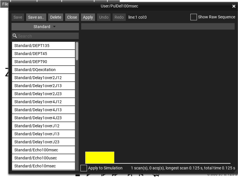
The menu selection opens the Sequence Explorer. The Sequence Explorer provides tools to manage and edit both “Standard” tabular pulse sequences and textually-defined “Industrial”-type Pulse Sequences. This window/interface can be very difficult to use on a small screen, such as an iPhone, and is therefore often disabled (unavailable) if the screen is too small.

Fig. 180 The sequence ‘Standard/PulDel100msec’ selected in the Sequence Explorer.
Sequence Selector
At the top left of the Sequence Explorer is a sequence category selection, and under it, a list of sequences that belong to the selected category. The sequences available in the regular menu appear in the category . Other sequences appear under the category , and user-created sequences appear under the category .
sequences are stored internally in a JSON structure. The easies way to edit these sequences is with the normal Edit Sequence… Sequence Editor. The JSON can also be directly edited by by advanced users. By default the raw JSON is hidden, but can be displayed by checking the Show Raw Sequence checkbox in the upper right corner.
sequences are written in a pulse-sequence language very similar to the Bruker industry-standard NMR pulse sequence language. Indeed, some Bruker sequences can be simulated un-modified in SpinDrops.
sequences can be of either form - either JSON or Industrial (Bruker-style).
Auto-Apply mode
When a sequence is selected from the list, it is shown in the Sequence Explorer, but not automatically loaded into the main SpinDrops simulation window. It is only displayed in the Sequence Explorer until the Apply button is clicked or when the checkbox Apply to Simulation is active, which enables automatic and immediate application of sequence selection or edits to the main SpinDrops simulation.
Industrial Sequence Language
The Industrial sequence language may look strange at first sight, but in reality is quite simple. The sequences are plain text files, and have three parts: an initial Definitions section, then the commands that generate pulses and delays, and finally a so-called Phase Programs section.
The language is very similar to the pulse language used by a well-known industrial NMR instrument manufacturer. Because of this, you can find a lot of example programs and ideas for pulse programs on the internet. However, be aware that the possibilities of a simulation software are somewhat different from an actual spectrometer, so not everything in the pulse programming is exactly the same.
The main difference in terms of the spin system is that in simulation we primarily look at a single, or a small number of spin systems, whereas in a real spectrometer, we’re interacting with a large number of similar spin systems with imperfect coupling to the experimental machinery. This means we can, in the simulator, specify exact starting states, and exact (and arbitrary) Hamiltonians – an impossibility for the experimentalist.

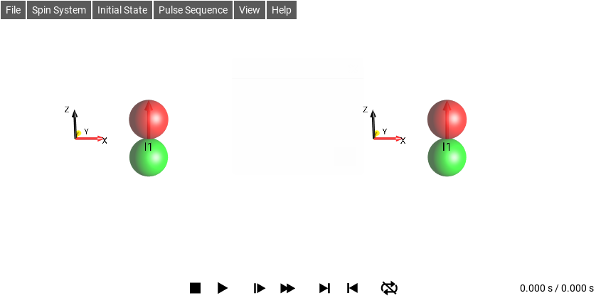
Fig. 181 \(\rho_0 = I_{2z}\)
Definitions
Before using any pulses, it is possible (though not necessary) to specify some values and operators that can be used later in the description of the sequence. Usefully, we set some parameters to the time durations needed to achieve a certain pulse rotation, or time duration for certain relaxations or mixing periods. Also we can specify arbitrary Hamiltonians to be applied during certain time periods, or specify literal Propagators that can be applied to the state. All of these definitions (using the define statement) should be at the beginning of the pulse program:
define pulse ...
define delay ...
define channel ...
define propagator ...
Pulse Definition
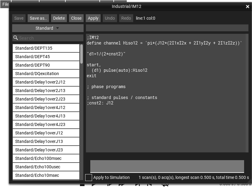
define channel Hiso12 = 'pi*(J12*(2I1xI2x + 2I1yI2y + 2I1zI2z))'
Delay Definition
define delay mydelay

"mydelay = 1s"
Hamiltonian Channel Definition
This Isotropic Mixing sequence uses a special type of definition to associate a channel in the pulse sequence with a specific Hamiltonian in the simulation. Later use of this “channel” in the experiment will apply this Hamiltonian to the simulation. This example creates a isotropic mixing Hamiltonian between spins 1 and 2 on a new channel called Hiso12.
define channel Hiso12 = 'pi*(J12*(2I1xI2x + 2I1yI2y + 2I1zI2z))'
The define channel statement can be used to define a channel
in terms of the Hamiltonian that will be in effect when the channel is
actively “pulsing” (that is, when this channel’s Hamiltonian is added
to the global system propagator Hamiltonian).
After the definition, a delay and the actual “pulsing” of the Hamiltonian are accomplished with the pulse program:
"d1=1/(2*cnst2)"                ; set the delay d1 to 1/(2*J12)

  (d1) pulse(auto):Hiso12       ; pulse the Hiso12 channel for duration (d1)
Propagator Channel Definition
Another kind of definition is the propagator definition, it defines a
special “channel” with an arbitrary propagator, rather than hamiltonian. In
order to make the propagator non-instantaneous, for display purposes,
a pseudo-Hamiltonian is internally calculated that, when applied for
\(1 s\) (using the “one second pulse” command 1sp), will
have the same effect as the requested propagator. This example is a
special case of the nop (no operation) propagator that does not
affect the system state at all, it is the same as the identity
operator:
define propagator nop = 'Id'        ; define the identity propagator

; To apply this propagator to the current state, make a 1-second pulse
; on it's channel:

  1sp:nop
To use the nop propagator again, for example, in the definition of a spin-selective inverting notA channel, it is necessary to assign the expression to a name, within the definition string:
define propagator nop = 'nop=2*Ie'       ; define a 2x2 identity matrix
define propagator not = 'not=[0,1;1,0]'  ; define a 2x2 inversion matrix
define propagator notA = 'kron(not,nop)' ; define a 4x4 spinA not propagator

  1sp:notA                               ; invert spin A in a 2-spin system
Pulse Lines
This is the “meat” of the pulse program, and it lies between the definitions and the first Exit. There are two main types of lines in this part of the pulse program:
pulse/delay lines which take up time and create either pulses or delays,
and calculation lines surrounded by double-quotes “”, which do not take up time but can alter values in the program.
These two types of lines may be interspersed. Here is an example pulse program:
"d1=1/(2*cnst2)"     ; set delay to 1/(2*J12)

start,
  p1          ; 90deg pulse
  d1          ; delay
  p2          ; 180deg pulse
  d1          ; delay
  (d1) pulse(auto):Hiso12    ; pulse the Hiso12 channel for duration (d1)

exit
The first line sets the delay variable d1 to the value
\(1/(2J_{12})\). The value cnst2 is a special symbol that
is set to the coupling J12 of the current simulation. If that value
is 0, the pulse sequence becomes ill-defined.
Next there is a label start, which does nothing, but marks a
place in the sequence where later looping commands (such as
acquisition loops) could jump back to (see for example, the phase
cycling experiments).
Then follows a (nonsense) sequence of p1, d1,
p2, d1, which are, respectively: 90 degree pulse,
delay of \(1/(2J_{12})\) (as defined earlier), 180 degree pulse,
and another delay of \(1/(2J_{12})\).
And finally, the line that starts with (d1) will create a
delay of d1 in parallel with a pulse of automatic length
(auto) on the Hiso12 channel – or in other words, the
isotropic mixing Hamiltonian will be in effect for a time of d1 or
\(1/(2J_{12})\). Such pulses with automatic length will
expand to fill the time of the line upon which it is specified – a
time determined by the longest of the other elements which are active
in parallel.
The exit is unnecessary in this pulse program, because there
are no phase programs to define, but it does not hurt to add it to
clarify where the program ends.
Preset Pulse Lengths
SpinDrops implicitly sets the maximum pulse amplitude to 10 Hz,
although this completely unrealistic. Pulse durations (p1 -
p31) are also automatically calculated for 90 and 180 degree
pulses on the available spins. On a real spectrometer, you would use
an experimental procedure to discover the pulse amplitude, and set
these values accordingly. SpinDrops adopts the same convention as
Bruker for the meanings of these pulse durations:
Pulse duration |
Meaning |
Pulse on channel |
|---|---|---|
|
duration of 90° pulse on spin I1 |
|
|
duration of 180° pulse on spin I1 |
|
|
duration of 90° pulse on spin I2 |
|
|
duration of 180° pulse on spin I2 |
|
|
duration of 90° pulse on spin I3 |
|
|
duration of 180° pulse on spin I3 |
|
Since these pulse durations are simply durations, is important to
remember to send the pulse to the correct “channel” so that it affects
the correct spin! This is done by appending a colon and the channel
to the pulse, ie: p3:f2, or p22:f3.
Preset Durations
There are also a number of pre-calculated durations available for use in pulse programs. These are constants describing the spin system’s coupling parameters: \(J_{12}\), \(J_{13}\), and \(J_{23}\). These are contained in the parameters:
delay duration |
meaning |
|---|---|
|
\(J_{12}\) |
|
\(J_{13}\) |
|
\(J_{23}\) |
The value of these parameters will change whenever the corresponding Spin System parameters/sliders are changed using the System Parameters Window.
Shaped Pulses
Using shaped pulses in the advanced language is quite similar to on an
actual spectrometer. Available pulses, and their names, can be seen
in the Pulse Explorer Window. It is also possible to import
shaped pulse files in either Bruker or Valerian format from there.
There is a small difference from the normal industrial syntax to make
setting the pulse names easier, it is done by assigning a pulse name
to the corresponding sp parameter, as follows to set the name
of the sp1 pulse file:
"sp1='Standard/sinc3_100.exc'"

start,
  ; shape pulse using default amplitude (typically in SpinDrops 10 Hz)
  p1:sp1

  ; a shaped pulse, flip defined, amplitude defined
  pulse(90 deg, 40 hz, auto):sp1 ph1
  pulse(180 deg, 40 hz, auto):sp1 ph2
  pulse(180 deg, 20 hz, auto):sp1 ph3

  p1:sp1 ph4 ; default amplitude (10 Hz), duration of p1

  ; hard pulse, defined amp and duration
  pulse(auto, 120hz, 2m)

  ; shaped pulses, defined flip and duration, implicit amplitude
  pulse(90 deg, auto, 10m):sp1 ph1
  pulse(180 deg, auto, 10m):sp1 ph2
  pulse(180 deg, auto, p1):sp1 ph3 ; duration of p1

exit
It is useful to think of a shaped pulse as a series of complex values with amplitudes between 0 and 1. These complex values determine the vector of the transverse RF magnetization while the pulse is being played.
Shaped pulse files usually contain (at least) two additional important parameters to assist in their use. These parameters must be set correctly in order for SpinDrops to calculate the correct pulse amplitude and duration.
a scaling parameter \(S_p\) (or “shape factor”) that tells you or the spectrometer how to set the pulse’s amplitude. Shaped pulses are typically either excitation or inversion pulses, that is, designed to tip spins either 90° or 180° degrees. A shaped pulse which is purely on-resonance (has no phase variation). Some pulses are designed for other purposes, but even those pulses’ amplitude information can be encoded this way. Bruker shape files store this value in a parameter called
$SHAPE_INTEGFAC. Varian .RF pulse files store this in a comment line tagged withINTEGRAL.The shape factor is defined relative to a hard pulse of the same flip angle. For example, say a shaped pulse was designed for 90°, has three pulse elements of equal duration, equal phase, and amplitudes of \(.1,.5, \text{ and } .8\), then the shape factor will be \(0.46667\).
Coming from the other direction, let’s say you calculate a shaped pulse that has an effective bandwidth of 20kHz, should be 15ms long, and whose maximum amplitude is 8 kHz, and is designed for a flip angle (arbitrarily) of 76°. An equivalent hard pulse (15 ms long, 76°) would have an amplitude of \(\frac{76/360}{15 \text{ ms}} = 14.074 \text{ Hz}\), so our shaped pulse’s \(S_p = \frac{14.074 \text{ Hz}}{8 \text{ kHz}} = 0.0017593\).
the pulse’s time-bandwidth product (\(T_p*\text{bw}\)) which is mostly used for pulses which are designed to act across a bandwidth. (\(T_p*\text{bw}\)) is simply the relationship between the pulse’s duration and its effective bandwidth. A pulse with \(T_p*\text{bw}=10\) played for \(1 \text{ ms}\) will affect a range of spins across a bandwidth of \(\text{bw}=\frac{10}{0.001}=10 \text{ kHz}\). Bruker shape files store this value in a parameter called
$SHAPE_BWFAC. Varian .RF pulse files store this in a comment line tagged withEXCITEWIDTHorINVERTWIDTH.
Acquisition
Adding an acquisition statement (either adc or go) to
a pulse sequence tells SpinDrops that you would also like to see the
FID created by the sequence. The simplest acquisition can be created
with adc - this statement will perform a readout of np
complex points at a bandwidth of sw (having a delay of \(1/sw\)
between each point). The readout of a single point is the
expectation value of the density matrix for the acquisition operator
– for example, for a single-spin system this operator is simply
\(I_{1}^{-}\) or \(I_{1}^{+}\) (depending on the whims of your
spectrometer manufacturer). For a two-spin homonuclear system, an
acquisition operator could be \(I_{1}^{-}+I_{2}^{-}\). For heteronuclear
systems there are separate acquisition channels, where all of the
spins of a type can be recorded on a single channel (ie all the H
together, and all of the C together).
We refer to a single acquisition as a trace, and we call the combination of one or more traces into a single vector an acquisition – this is because as a processing shortcut, spectrometers often only record the traces into temporary buffers which contain, at any given time, some phase-modulated summation of traces until the current time. SpinDrops calculates and displays traces separately to let the user see what is really happening in the experiments. The combined acquisition is also displayed (or it will be - this feature is still being developed!).
Here is a simple pulse-acquire program, it is simply a 90° pulse followed by an acquisition.
start,
  p1
  adc

exit
Assuming that the Initial State is \(I_{1z}\), and that spin 1 has some offset, we can see the trace recorded by this sequence (Fig. 182).

Fig. 182 Pulse Acquire
Exit
The exit command ends the pulse program execution. There can
be multiple exit commands in the text file, but the first one
will always be the end of the sequence. A pulse program does not need
to have an exit, if there are no Phase Programs, since
it just serves to separate the body of the sequence from their
definition.
exit
Phase Programs
Phase Programs must be forgiven for their archaic name dating to an earlier era of computing terminology. What is meant here by “program” is simply a repeating sequences of phases. Values from this sequence can be referenced from pulses and acquisitions. When so referenced, they return the phase at the list’s current position, which of course starts at the first position and advances either explicitly or implicitly, depending on what is happening in the pulse sequence.
In the case of pulses, specifying a Phase Program along with a pulse determines what phase the pulse will have. The current position of all of the Phase Programs is implicitly advanced to the next element every time there is a go command. This automatic increment can be avoided by using the related command gonp used (which cryptically means “go with no phase increment”).
; phase programs
ph2 = 0 1 2 3