Sequence Editor
With a little practice it is easy to modify existing sequences or to build a new pulse sequence from scratch using the sequence editor. New sequence elements can be created and existing sequence elements can be changed, duplicated (copy/paste) or moved to different positions in the sequence. In order to change or multiply a sequence element it needs to be activated.
Activation of a Pulse Sequence Element
Sequence elements (pulses or delays) can be activated by a tap or click. In the example shown in Fig. 163, sequence element #3 (a 180°x pulse) has been activated. Double-clicking / -tapping a sequence element opens an input panel for the element.
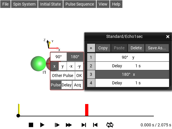
Fig. 163 Activated 180°x pulse and its editing panel
Modification of a Sequence Element
The associated input panel of an activated sequence element allows you to change a delay to a pulse or vice versa, modify the flip angle and phase of a pulse, or to change the duration of a delay. The duration of delays can be defined in absolute time units (“s”, “ms”, “μs”) or in multiples of the inverse coupling constants, e.g. \(0.5/J12 = 1/(2 \cdot J12)\).
Creating a New Sequence
New Homonuclear Sequence
You can build a new pulse sequence using the sequence editor. Let’s say you wanted to create the homonuclear sequence
90°y - 250 ms - 180°x - 250 ms.
Start with an existing Homonuclear sequence, for example , then open the editor with . This will display the Tabular Pulse Sequence Editor. This sequence consists of a single entry, a Delay of 1 second. Select this entry by double clicking/tapping on it.
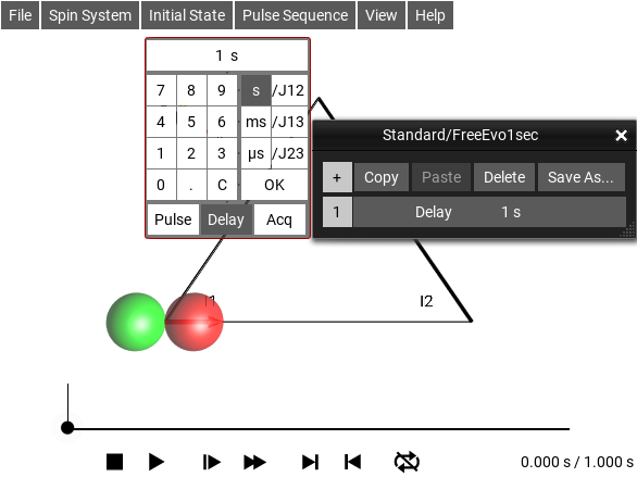
Fig. 164 Editing the Delay = 1s Sequence
The current list entry can be modified by the associated input panel, which is displayed at the left of the sequence list. To change the delay to a pulse, touch Pulse. The element will change to a pulse, and the input panel will change to offer pulse parameters.
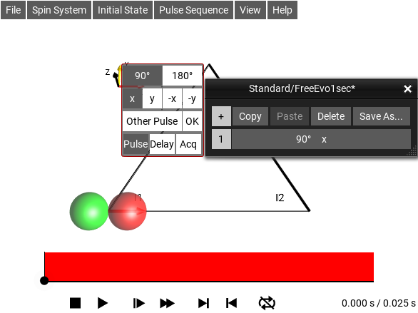
Fig. 165 Delay element changed to a Pulse
The default pulse is a 90°x. In order to change it to 90°y, touch y.
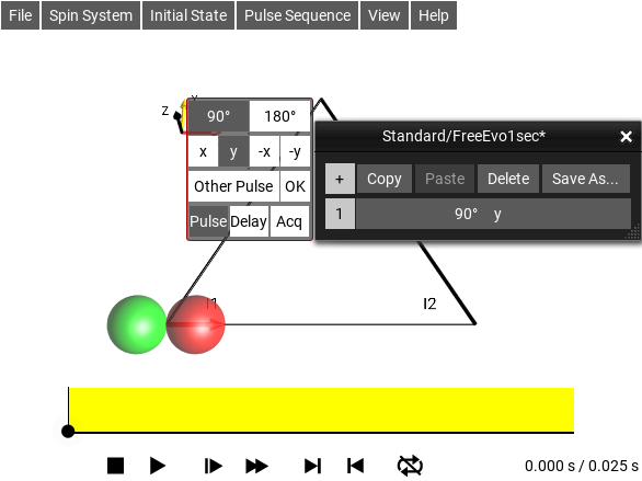
Fig. 166 Phase of pulse changed to y
This changes the entry of the sequence list to 90°y. In order to add another entry to the Sequence List, touch the + button.
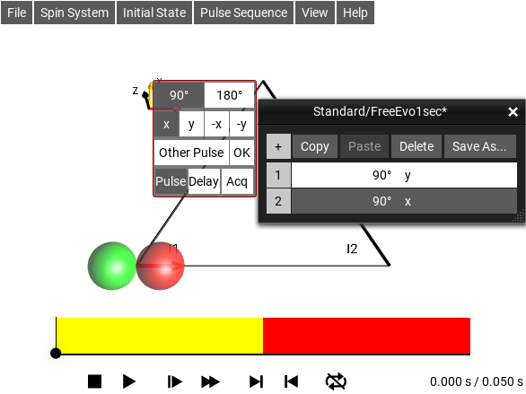
Fig. 167 Added a new second pulse
This creates a second entry in the sequence list, which by default is a 90°x pulse. The dark background of the second list entry indicates that this is the “active” list entry. (An inactive list element with a white background can be activated by a tap). To change the pulse to a delay element of 100 ms, click Delay, and then to change the delay from the default 100 ms to 250 ms = 0.25 s, enter “250” in the input panel.
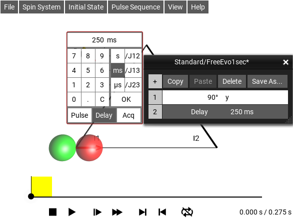
Fig. 168 250 ms delay added after the 90°y pulse
To save this sequence, click the Save As… button, and give the new sequence a name. The new sequence (for example “My Sequence”), will appear under the menu .
New Heteronuclear Sequence
To create a new heteronuclear sequence with spin-selective pulses, select an existing Heteronuclear sequence, such as . Selecting the menu or double-clicking the sequence display will open the Tabular Pulse Sequence Editor.
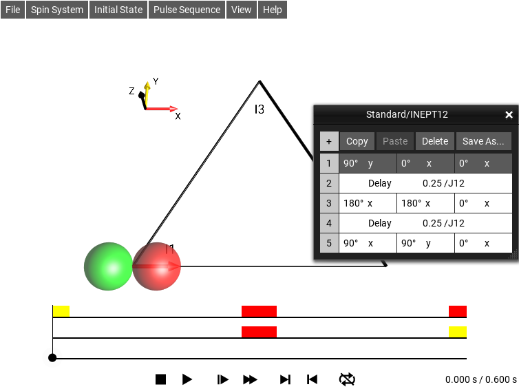
Fig. 169 Editing the INEPT12 Sequence
Delete the existing sequence by clicking the Delete button several times, until the sequence is empty: (the sequence title Standard/INEPT12* now has a * added to the end indicating that there are unsaved changes to the sequence)
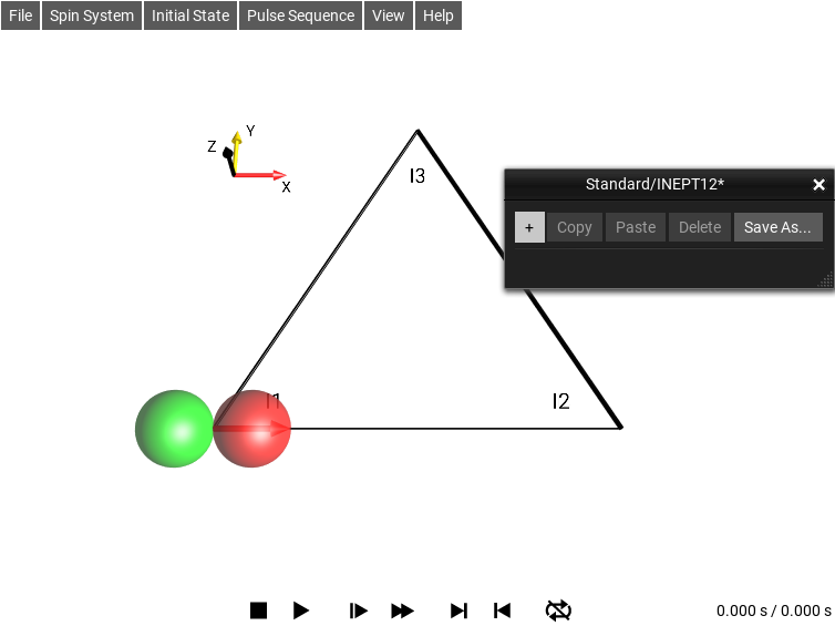
Fig. 170 Editing the Delay = 1s Sequence
In the heteronuclear case, the default new sequence element (created by clicking on +) is a 90°x(I1) pulse, i.e. a spin I1-selective 90°x pulse.
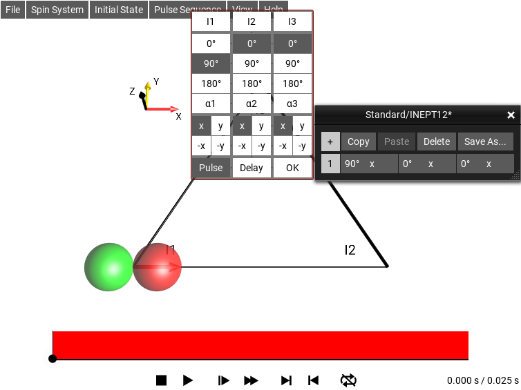
Fig. 171 Editing the Delay = 1s Sequence
Suppose the first pulse sequence element should be an I1-selective 90°y pulse which is applied simultaneously with an I3-selective 90°(−y) pulse.
To create this pulse sequence element, first select phase “y” for the I1-selective 90° pulse. Then select 90° for the flip angle of the I3-selective pulse and finally select phase “−y” for this pulse:
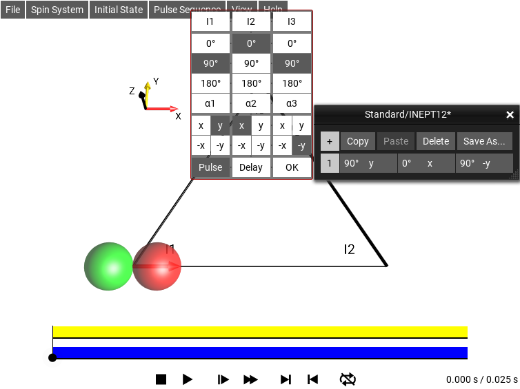
Fig. 172 Editing the Delay = 1s Sequence
As shown in the Sequence List, (blue ellipse), the first sequence element consists of a simultaneous 90°y(I1) and a 90°−y(I3) pulse.
Saving a Modified Sequence
The sequence name still has a * at the end, and it is no longer the Standard/INEPT12 sequence, so it should be stored under a new name. To save the sequence, click the Save As…, and type the new sequence name in the box (FANCY). After saving, the sequence will appeear under .
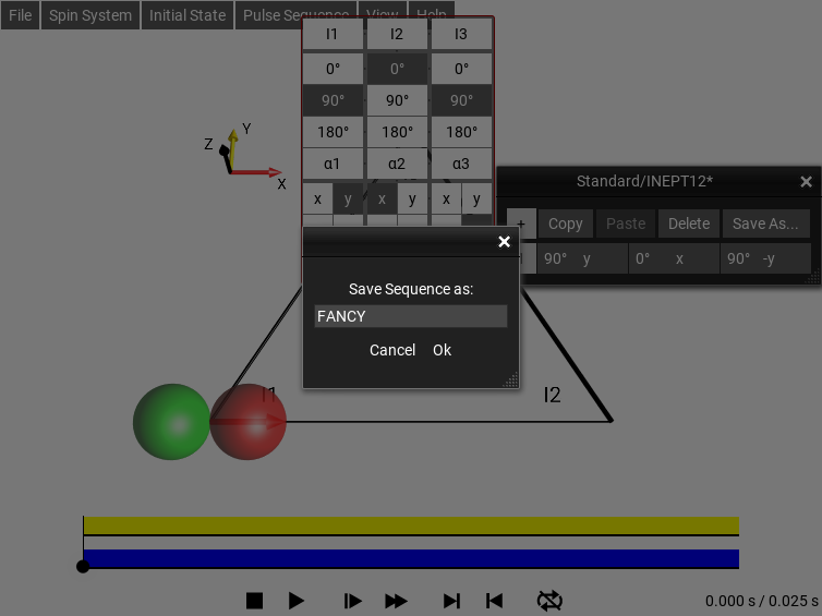
Fig. 173 Saving the sequence with a new name
Modifying an Existing Pulse Sequence
Let us consider the sequence shown graphically below. Pulses that act selectively on spins I1, I2 or I3 are displayed in the first, second, or third column, respectively.
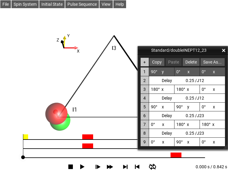
Fig. 174 The ‘z1 -> zzz’ Sequence
It is also possible to display a list of the individual pulse sequence elements by choosing (see list shown in Fig. 174).
This heteronuclear pulse sequence consists of seven pulse sequence elements, which are consecutively numbered in the left column of the list. Elements 1, 3, 5, 7, and 9 are spin-selective pulses, where the first, second, and third column corresponds to I1-, I2-, and I3-selective pulses. Elements 2, 4, 6, and 8 are delays.
In order to modify a given pulse sequence element, it must be “activated”, which can be achieved by double tapping the row in the edit window:
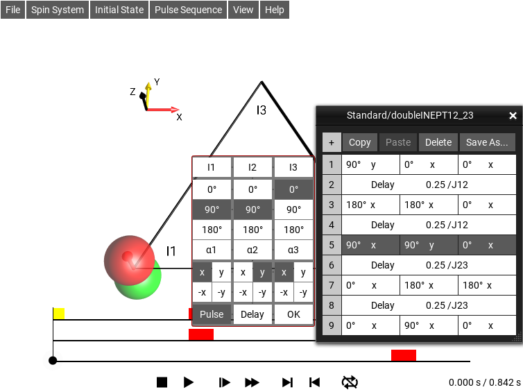
Fig. 175 Editing element 5
The activated pulse sequence element (in this example, element 5) is highlighted in the sequence list by white letters on a dark background.
The associated input panel allows you to modify the active pulse sequence element.
For example, the I2-selective 90°y pulse can be eliminated by choosing a flip angle of 0°:
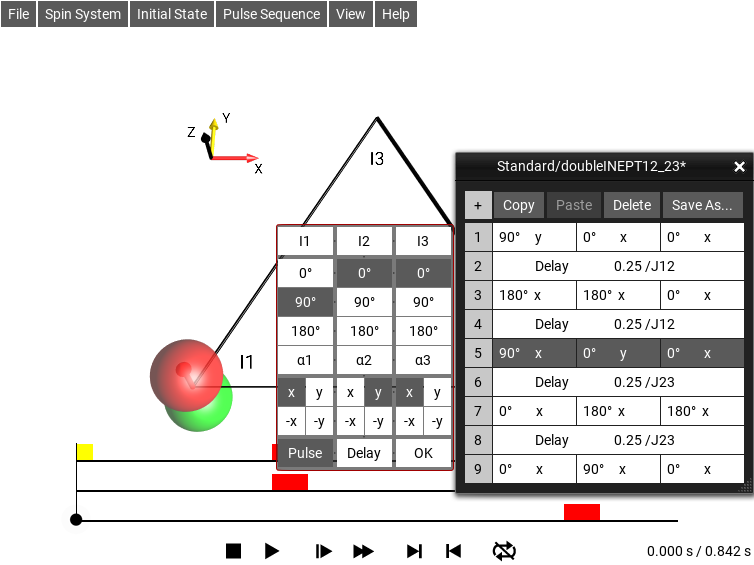
Fig. 176 Editing element 5
The modification is instantly displayed both in the sequence list and in the sequence plot.
It is also possible to choose a flip angle different from the most common values (90° or 180°) by touching α1. As shown below, this will open an additional input panel that allows you to numerically enter a desired flip angle.
Touching the α1 button opens the additional input panel. The display “90°x(I1)” at the top shows the current flip angle (90°) of the spin I1-selective pulse with phase x.
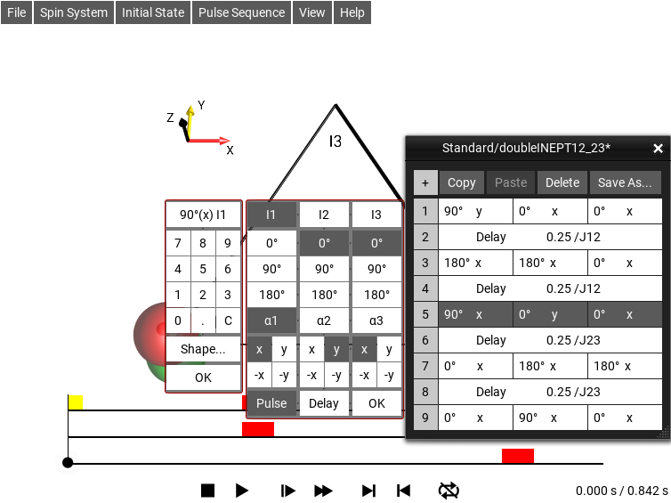
Fig. 177 Editing element 5
For example, we can change the flip angle to 60° by touching the corresponding keys (6 0) of the input panel:
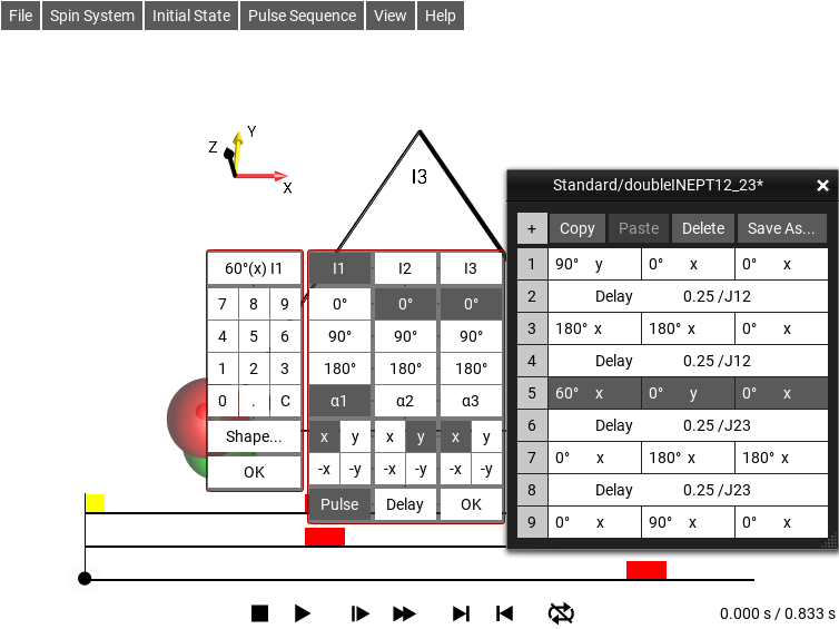
Fig. 178 Changed flip angle to 60°
60° is displayed numerically in the Sequence List as well as graphically in the sequence plot.
The additional input panel at the left can be closed with the OK button. The input panel in the center can be closed and the currently “active” pulse sequence element can be “deactivated” by touching the OK button of the center panel.
Moving Sequence Elements to Different Positions
A sequence element is moved by touching its entry number (such as 5) and dragging the row to the desired new position.
Copy/Paste
An activated pulse sequence element can be copied and pasted using the corresponding buttons at the bottom of the sequence list. Initially, the Copy and the Paste buttons are inactive.
Activating a sequence element makes the Copy button active.
Touch the Copy button to store the active pulse sequence element in an internal buffer. When the buffer is loaded, the Paste button becomes active.
Touching the Paste button inserts the stored sequence element after the currently activated sequence element. If no sequence element is activated, the stored sequence element is inserted at the end of the sequence.
Deleting Sequence Elements
Pulse sequence elements can be deleted with the Delete button.
The Delete button removes the activated sequence element from the list. Remember that a sequence element can be activated by a double tap/click.
Creating Acquisition Elements
Pulse sequence elements can be changed into acquisition elements with the Acq button.
Acquisition elements are much like pulse elements, but instead of having an editable pulse duration, the number of acquired points is fixed and the bandwidth of the acquisition is adjustable.
Display and Duration of Pulses
Normally, the simulations assume ideal pulses, i.e. the effects of frequency offsets and couplings are not taken into account during the pulses.
In order to make the pulses visible in the sequence plots and to be able to distinguish pulses of different flip angles based on the width of the displayed rectangles, a low default pulse amplitude (Rabi frequency) of only 10 Hz is assumed. Thus, the duration of a 360° pulse is 1/(10 Hz) = 0.1 s = 100 ms, the duration of a 180° pulse is 50 ms, and the duration of a 90° pulse is 25 ms. However, as frequency offsets and couplings are neglected (not included in the Hamiltonian) during the duration of the pulses in the simulations, the pulses have the same effect as ideal delta pulses of negligible duration.
The setting Ideal Pulses can be used to enable or disable the frequency offsets and couplings of spins during pulses.
Additional care has to be taken in the case of heteronuclear experiments, where pulses can be selectively applied to individual spins. In this case, it is important to remember that during the duration of a pulse, offsets and couplings do not evolve, even if a particular spin is not irradiated. This is indicated by a grey rectangle in Fig. 179. Also note that simultaneously applied pulses with different flip angles are displayed with different widths and are centered in the sequence plot. The example at the right shows a zoom of the simultaneous 180°x (red rectangle) and 45°y (yellow rectangles) pulses in the DEPT-45 sequence. Note the grey rectangle indicating the pulse duration, which has been enhanced here for better visibility.
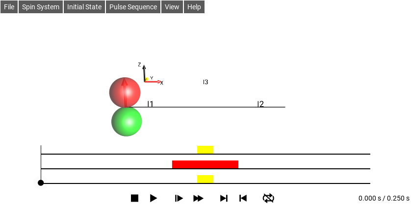
Fig. 179 Pure pulse (drift Hamiltonian omitted) region.